Enjoy FREE SHIPPING on every order, fully insured for your peace of mind.
Description
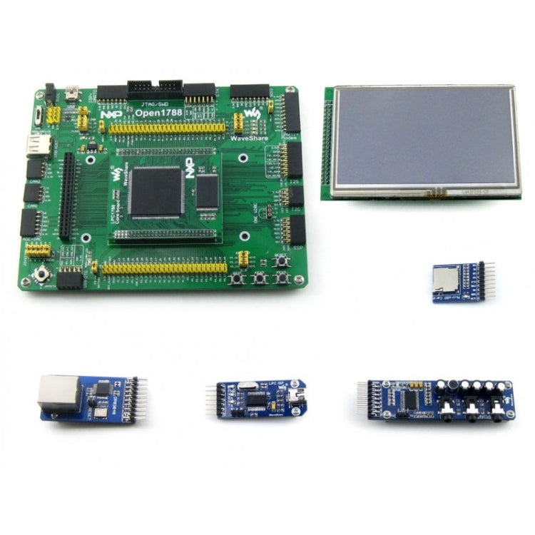
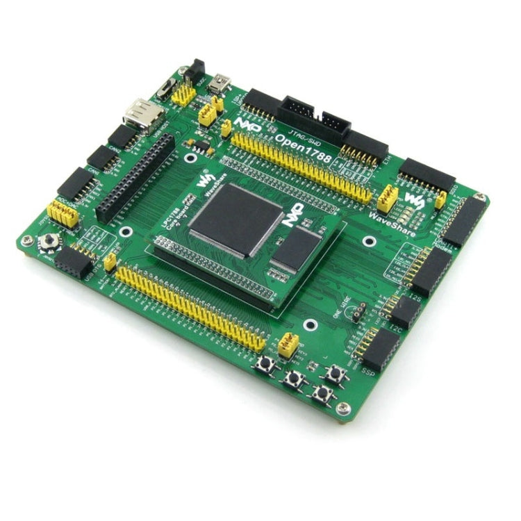
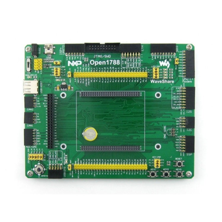
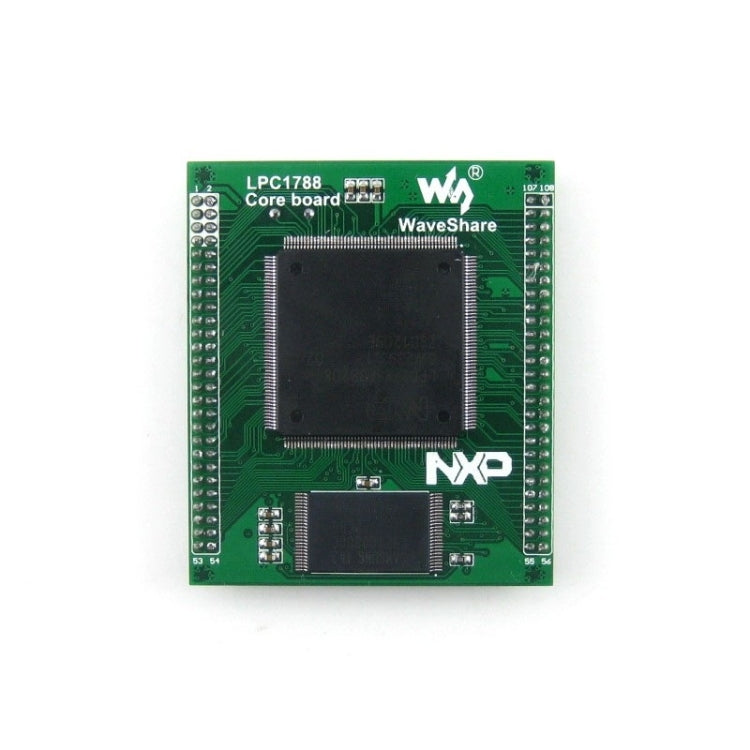
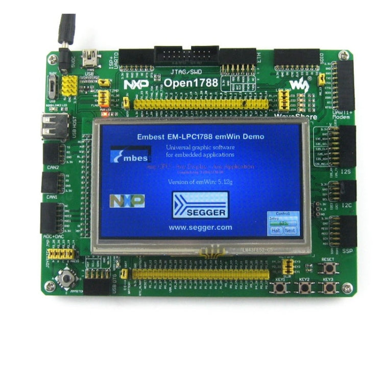
Open1788 is an LPC development board designed for the LPC1788FBD208 microcontroller, consists of the mother board and the MCU core board Core1788.
The Open1788 supports further expansion with various optional accessory boards for specific application. The modular and open design makes it the ideal for starting application development with NXP LPC series microcontrollers.
What is on board
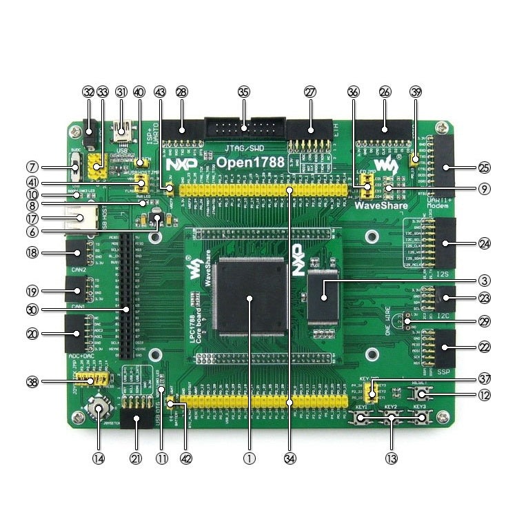
1. LPC1788FBD208 (core board): The high performance LPC MCU which features:
- Core: Cortex-M3 32-bit RISC
- Operating Frequency: 120MHz Max
- Operating Voltage: 2.4-3.6V (3.3V typical)
- Package: LQFP208
- I/Os: 165
- Memories: 512KB Flash, 96KB SRAM, 4K EEPROM
- MCU communication Interfaces:
-- 1 x LCD, 1 x 10/100 ETH MAC, 1 x GP DMA Controller
-- USB Device/Host (Onchip PHY and DMA Controller)
-- 5 x UART, 3 x SSP, 3 x I2C, 1 x I2S, 2 x CAN,1 x SDIO
-- 8 x 12Bit ADC, 1 x 10Bit ADC, 1 x DAC, 1 x MOTOR PWM
-- 6 x GP PWM, 1 x Quadrature Encoder Interface, 1 x EMC
- AD & DA converters: 3 x AD (12-bit, 1μs, shares 24 channels); 2 x DA (12-bit)
- Debugging/Programming: Supports JTAG/SWD (serial wire debug) interfaces, supports ISP via UART
2. H57V1262GTR-75C (core board): 2PCS x 128M Bit SDRAM
3. K9F1G08U0B (core board): 1G Bit NandFlash
4. SST39VF3201 (core board): 32M Bit NorFlash
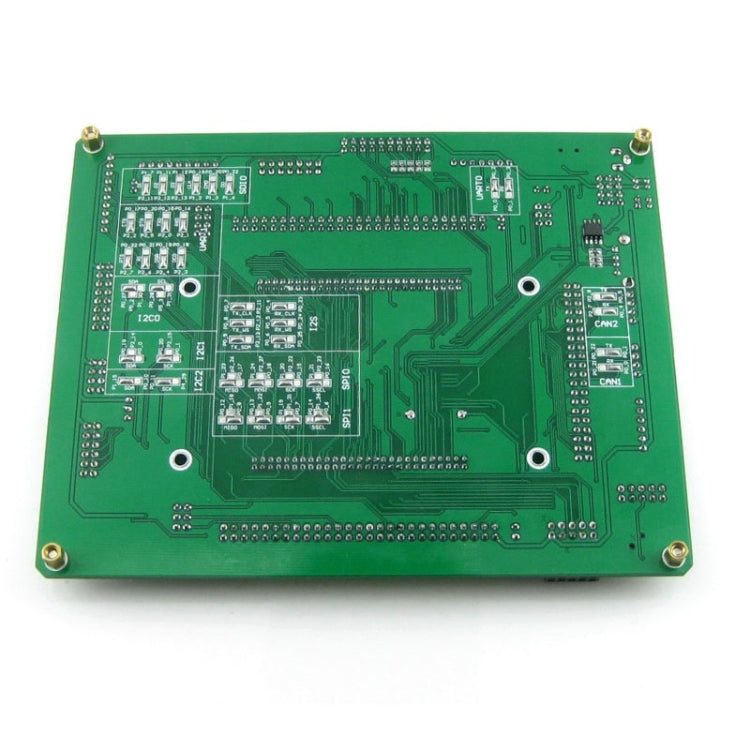
5. LM3526-L (mother board bottom side): Onboard USB power switch and over-current protection
6. AMS1117-3.3, 3.3V voltage regulator
7.Power supply switch
8. Power indicator
9. LEDs: Convenient for indicating I/O status and/or program running state
10. USB communication LED1: USB GOOD LINK1
11. USB communication LED2: USB GOOD LINK2
12. Reset button
13. User key: Convenient for I/O input and/or interact with running code
14. Joystick: Five positions
15. 12M crystal oscillator (core board): Used to boost operating frequency by frequency multiplication
16. 32.768K crystal (core board), for internal RTC with calibration
17. USB type A interface: For connecting USB devices such as USB flash drive
18. CAN2 interface: Communicates with accessory boards which feature the CAN device conveniently
19. CAN1 interface: Communicates with accessory boards which feature the CAN device conveniently
20. AD+DA interface: For AD/DA testing
21. USB OTG transceiver interface: For connecting USB OTG transceiver module
22. SPI0 | SPI1 interface: Easily connects to SPI peripherals such as DataFlash (AT45DBxx), SD card, MP3 module, etc.
23. I2C1 | I2C2 interface: Easily connects to I2C peripherals such as I/O expander (PCF8574), EEPROM (AT24Cxx), etc.
24. I2S | I2C0 interface: For connecting I2S and/or I2C modules such as UDA1380 module, FRAM FM24CLxx, etc.
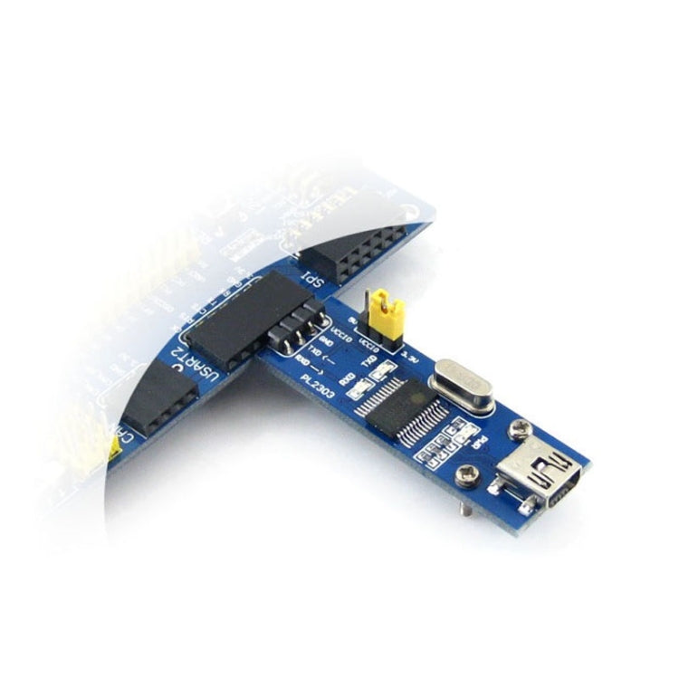
25. Modem | UART1 interface: For connecting Modem and/or UART modules such as RS232, RS485, USB TO UART, etc.
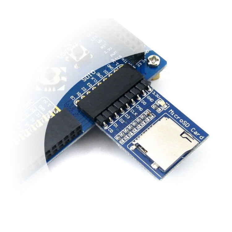
26. SDIO interface: For connecting Micro SD module, features much faster access speed rather than SPI
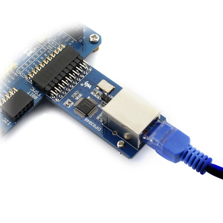
27. Ethernet interface: Easily connects the MCU to ethernet network by using an additional ethernet module, such as DP83848 Ethernet Board
28. ISP | UART0 interface: For connecting ISP and/or UART modules such as RS232, RS485, USB TO UART, etc.
29. ONE-WIRE interface: Easily connects to ONE-WIRE devices (TO-92 package), such as temperature sensor (DS18B20), electronic registration number (DS2401), etc.
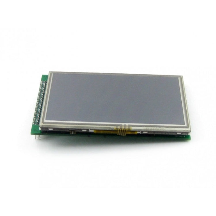
30. LCD interface: For connecting to 4.3 inch touch screen LCD through an adapter
31. USB mini interface: Used for establishing USB communication between PC and the LPC development board
32. 5V DC jack
33. 5V/3.3 V power input/output: Usually used as power output, also common-grounding with other user board
34. MCU pins connector: All the idle pins are accessible on expansion connectors for further expansion
35. JTAG/SWD interface: For debugging/programming
36. LEDs jumper
37. User key jumper
38. Joystick jumper
39. SD card detect jumper
- Short the jumper to enable SD card detection function
- Open the jumper to disconnect from I/O port
40. USB enable jumper
- Short the jumper to enable USB
- Open the jumper to disconnect from I/O port
41. USB HOST jumper
- Short the jumper when using USB HOST
- Open the jumper to disconnect from I/O port
42. VBAT selection jumper
- Short the jumper to use the onboard battery
- Open the jumper to connect the VBAT to other external power
43. VREFP selection jumper
- Short the jumper to connect VREFP to VCC
- Open the jumper to connect VREFP to other custom pin via jumper wire
Package Contents
1. Standard Package
- Open1788 development board x 1
- LPC ISP (mini) x 1
- USB type A plug to mini-B plug cable x 1
- 4-pin 2-pin wires pack x 1
- USB power cable x 1
- Software CD x 1
2. Accessory Boards Package
- 4.3inch 480x272 Touch LCD (B) x 1
- DP83848 Ethernet Board x 1
- Micro SD Storage Board x 1
- Ethernet Cable x 1
- 4.3inch LCD screws pack x 1
Cancellation Policy:
We at Order2india strive to provide you with the best possible experience while you shop with us online. Since our orders are shipped from overseas , we try to reduce the handling time as much as possible by quickly processing the orders , Hence any cancellation request , has to be placed within 24 hours of placing the order. The refund amount will be credited back on your original mode of Payment. .
Warranty:
All our products comes with a default 90 days seller replacement warranty against manufacturer defect as a service and reassurance to our customers. Order2india will take care of all logistics to and from the manufacturer/supplier for replacement . If within 90 days of delivery ,any problem is found with our product , please contact our customer support and we would replace it for you absolutely free.
Return Policy
Our return policy is outlined below. The policy reflects the reality that our products are sourced from suppliers located outside India and is formulated keeping in mind the costs and time involved in the logistics, both in the forward direction (i.e. shipping products to India from the suppliers) and reverse direction (i.e. shipping returned products back to the suppliers).Certain products are not eligible for return or refund as below
Return Process & Timeline
For eligible products, the policy is summarized below. Please note that Returns that do not meet the Return Process and Timeline below will not be eligible for a refund.
|
|
Allowed Time Line |
Return Process |
|
Due to Damage in transit |
Within 24 hours of Delivery |
Inspect package before taking Delivery and if damaged REJECT package and DO NOT take delivery from the courier and Send email to support@order2india.com within 24 hours of rejecting the delivery so we can process your refund. |
|
Dead on Arrival or mal-functioning product |
Within 15 days of Delivery |
Contact us or email us at support@order2india.com within 15 days of delivery with details of the problem. |
|
Incorrect Order (e.g. model, brand, color or size different from what was ordered) |
Within 15 days of Delivery |
Contact us or email us at support@order2india.com within 7 days of delivery with details of the problem. |
We process your payment information securely. We do not store credit card details nor do we have access to your credit card information.
If you receive a parcel with missing, incorrect, or secondary packing items, please contact us within 7 days of delivery with relevant proof. Order2india will assess the situation and provide resolution based on the extent of the damage.
You may also like
Recently viewed


